
Talk:Fresnel equations
| This It is of interest to the following WikiProjects: | |||||||||||
| |||||||||||
.jpg)
Form of equations[edit]
There seems to be an incoherence on this page: while in the linked articles the transmission and reflection coeficient are defined as ratios of Amplitudes (in this case of the E-Field), the equations in this article seem to describe a ratio of intensities.
I see two possibilities to correct this:
- make clear, that the coefficients describe intensities (perhaps remove the links to the other articles or change these):


with the intensities of the incident light and if the reflected light.


- change the equations to fit Amplitudes (I don't know wether this would correspond to the graphs any more):


with the corresponding amplitudes of the electric field


I would prefer the second possibility since it corresponds to the majority of the literature I have at hand - but I don't have time to check and replace the graphs right now - I'll be back when I have more time and take care of this if nobody else has until then...—The preceding unsigned comment was added by Nanomage (talk • contribs) .
- This is probably a conflict between the optical usage, which cares mostly about intensity, and general electromagnetic wave usage, which cares more about amplitude. I've clarified that the equations refer to intensity coefficients. (Note: most literature I have uses small r and t for amplitude coefficients, and large R and T for intensity coefficients, if you decide to change it.) -- DrBob 16:48, 8 September 2005 (UTC)
I also think that the equations for the reflection and transmission coefficients of the electric field should be given, further more their relation to the intensities should be emphasized and not only linked to. Some people care about phase, for example when going from low index to high index there is a 180 phase change at reflection, but when going from high index to low there isn't. Also r^2+t^2 is not equal to 1. Unlike the sum of the intensities which take into account the different velocities of the fields in different media. I think that ignoring amplitudes is simpler but will lead to misunderstandings as the texts and many people refer to amplitudes. —Preceding unsigned comment added by Eranus (talk • contribs) 16:16, 21 July 2008 (UTC)
- Adding the amplitude form in addition to the intensity form seems fine to me, but it has to be very carefully written. See my comment further down in this section. The formalism needs to be made very clear, since there are incompatible sign conventions and other differences in the mathematical formalism between different presentations of the amplitude equations.--Srleffler (talk) 16:31, 21 July 2008 (UTC)
-Shouldn't also be pointed out that the refractive index used for these equations is a complex number? --an anonymous Raptor 10:00,07/10/05 CET
I think the equation for p-polarization is wrong. From what I've seen in the literature, the following should be the equation:

—The preceding unsigned comment was added by 132.206.69.48 (talk • contribs) .
- I haven't checked the math here, but be aware that the form of the equations depends on an arbitrary choice of sign convention. Different authors make different choices. --Srleffler 01:01, 18 February 2006 (UTC)
Why not include the equations for both intensity and amplitude and make clear which is which and where each is used?-4.232.0.63 17:06, 7 August 2006 (UTC)
- That could work, but the amplitude form is a little more complicated pedagogically. The exact form of the equations depends on a choice of sign convention, and in addition I have seen at least three incompatible mathematical treatments, that essentially define "amplitude" differently. Which treatment is most common depends on what field you're in. The intensity formulism has the advantage of avoiding these difficulties. Differences in sign conventions and definitions often leads to Wiki articles with outright errors, as different editors modify equations without understanding the formalism or realizing that what appears in their textbook might not be correct given the definitions used in the wikipedia article.--Srleffler 00:32, 8 August 2006 (UTC)
Power ratio or intensity ratio? They are differnt!--Antonysigma (talk) 16:55, 1 May 2011 (UTC)
Please state somewhere that the incident theta angle is in the range [0,90] degrees, otherwise the trigonometric expressions are not valid. — Preceding unsigned comment added by Ed.fuentetaja (talk • contribs) 01:57, 19 August 2019 (UTC)
- How could the angle of incidence be greater than 90°? Think about it. This is physics, not math.--Srleffler (talk) 02:54, 23 August 2019 (UTC)
spelling polarise or polarize[edit]
All references at my disposal use z not s in all forms. --4.232.0.63 16:52, 7 August 2006 (UTC)
- "Polarise" is an accepted British Commonwealth spelling. Wikipedia's Manual of Style prescribes that all varieties of English are accepted, although they should not be mixed in a single article. If a particular subject is not directly tied to a particular country, it stays in whichever variety of English was first used in that article.--Srleffler 00:32, 8 August 2006 (UTC)
Imprecise physics[edit]
Some physics in the article are imprecise. Approximations or assumptions made for some formulae are not clearly spelled out (e.g. the paragraph on reflectivity of a dual-surface window and the next paragraph on Fabry-Perot interference directly contradict each other), and other assumptions may be misleading (i.e. mentioning dielectric materials, but neglecting parelectric materials). Contrary what is claimed in the article, Fabry-Perot interferometers cannot be used to create perfect mirrors or reflection-free lenses (causality, i.e. the Kramers-Kronig relations, dictates that there is always some absorption.)
I spent a while editing the article, but Wikipedia lost the edited version on trying to preview it. I'm not sure I want to go through that frustration again, so someone else has to correct the article. —Preceding unsigned comment added by 218.186.8.10 (talk • contribs)
- Sorry about the lost edit. That rarely happens, although the wiki has been a bit flaky the last four days or so. When you do get an error screen on "preview" or "save" always try your browser's back button. This generally returns you to the edit screen with no loss of text. Thanks for the suggestions.--Srleffler 19:58, 6 November 2006 (UTC)
This article needs to include the phase shifts associated with reflection and transmission from these surfaces. —Preceding unsigned comment added by 140.247.5.34 (talk) 17:17, 27 November 2009 (UTC)
I think the Fresnel equations should be expressed in terms of the amplitude instead of intensity. This will bring out important features such as the phase shift upon reflection when going from a low to a high index material. —Preceding unsigned comment added by 74.104.44.203 (talk) 19:34, 27 November 2009 (UTC)
This article, like almost every textbook ever, makes the assumption that the relative magnetic permeability equals 1. This is all fine until you are trying to compute the reflection on a iron plate. If you derive the Fresnel equations without neglecting the magnetic permeability, then you quickly notice that the refractive index is not what should appear in them. Instead, we should see admittances (for the perp case) or impedances (for the para case). Refractive index: ; admittance ; impedance . When equals 0, the admittance and the refractive index both look like (the gets simplified), hence the confusion that is repeated everywhere. But fundamentally, this is wrong. We obviously cannot correct the main equations since they're in every textbook (except Stratton's, he got it right, even though he used the weirdest notations ever), but having a paragraph for the case wouldn't hurt, especially since the formulas aren't even more complicated. Niriel (talk) 00:25, 28 October 2014 (UTC)


- The value of the two approaches depends on what one's goal is. If one is interested in electromagnetic theory, it makes sense to derive the more general form of the equations. If one is interested in optics, the case is the better form, since one wants to know how reflection and transmission vary with index of refraction, and dielectric materials are really the primary area of interest.

- I agree that a paragraph on the more general form would be a good addition to the article. Why don't you write one? It would be best if you follow a reference, and provide a citation to it. This makes it easier for other editors to catch typos in your work, and to ensure that the formulas stay correct as other people edit them. You could follow Stratton but convert the notation to match this article's , if that is not too complicated. Don't unnecessarily introduce a very different notation—that will just be confusing.--Srleffler (talk) 01:32, 28 October 2014 (UTC)
Redirection[edit]
Would it be okay to redirect a Fresnel's law page to this page? —The preceding unsigned comment was added by Wk muriithi (talk • contribs) 13:03, 24 January 2007 (UTC).
- Sounds good to me. Dicklyon 04:18, 25 January 2007 (UTC)
Metals absorb light?[edit]
The article says "For materials which absorb light, like metals and semiconductors, n is complex, and Rp does not generally go to zero." But don't clean metallic surfaces essentially not absorb light? Is this right? —Ben FrantzDale (talk) 21:56, 30 April 2008 (UTC)
- It is correct: metals are absorptive. A lot of light is reflected at the surface, but what gets into the metal is absorbed over a very short propagation distance. I think silver and aluminum reflect 90–95% in the visible. The rest is absorbed (assuming the metal is thick enough.)--Srleffler (talk) 23:22, 30 April 2008 (UTC)
- Interesting. Obviously copper absorbs in the blue end of the visible spectrum. This leads me to another question: how does mirror reflection work at an atomic scale? That is, when the continuum assumption breaks down, materials can't have a smooth surface yet light behaves as though surfaces are smooth. If it didn't, one couldn't make a lens and a polished crystal, which has atomic-scale star steps between crystal planes, wouldn't reflect like a mirror but would instead reflect like, well, stair steps. —Ben FrantzDale (talk) 01:16, 1 May 2008 (UTC)
- Atoms are about 0.1 nm wide. Atomic spacing in solids is maybe a few tenths of a nanometer. Visible light has a wavelength of ~400–700 nm. The light doesn't see roughness below about the 100 nm scale. X-rays have wavelengths comparable to atomic radii and/or lattice spacings, which is why reflecting x-rays off of crystalline solids produces x-ray diffraction.--Srleffler (talk) 01:58, 1 May 2008 (UTC)
- Interesting. Obviously copper absorbs in the blue end of the visible spectrum. This leads me to another question: how does mirror reflection work at an atomic scale? That is, when the continuum assumption breaks down, materials can't have a smooth surface yet light behaves as though surfaces are smooth. If it didn't, one couldn't make a lens and a polished crystal, which has atomic-scale star steps between crystal planes, wouldn't reflect like a mirror but would instead reflect like, well, stair steps. —Ben FrantzDale (talk) 01:16, 1 May 2008 (UTC)
- Thanks. That's basically what I assumed, but have never had it stated explicitly. Do you know where I would find the quantum-mechanical equations describing light interacting like that with a "bumpy" surface? It seems like one aught to be able to find an "effective surface geometry" for nanoscale-rough surfaces such that physics "acts" like that's where the surface is. —Ben FrantzDale (talk) 11:34, 12 May 2008 (UTC)
Optical coupling[edit]
I've heard the term "optical coupling" and "wetting out" to describe what happens when optical films come in contact. I assume this is the transition from a film-air-film sandwich to a film-film sandwich as the air thickness starts to get well below the wavelength of the light. Could someone point me to more information on that? 155.212.242.34 (talk) 14:16, 19 May 2008 (UTC)
- It may be related not to the air film being less than a wavelength, but rather to the gap becoming small enough that intermolecular forces (van der Wahls??) pull the surfaces together. This effect is used in optical contacting to bond optical surfaces together. The surfaces are rubbed together with a fluid in between. Surface tension/capillary forces in the fluid pull the surfaces close enough together that van der Wahls or something similar takes over. It can be used to make both temporary and permanent bonds, but I don't know much more about it than that.--Srleffler (talk) 17:10, 22 July 2008 (UTC)
- I think the original poster is onto something with regard to this being a wave-like effect. Fyneman has a great description of how light acts in QED in which you add up all possible routes a photon could take; this explains how a photon can appear to "decide" not to reflect off the first surface of an AR coating. As I understand it, optical coupling should work like this: Suppose you have two pieces of glass with a combined four surfaces. If you bring them close together you'll start getting Newton's rings. At one wavelength apart, you'll get constructive interference from the path that bounces off the 3rd surface. At 1/4 wavelength you get destructive interference because light bouncing off the 3rd surface is 180° out of phase with light hitting the 2nd surface. At less than 1/4 wavelength of air gap, I would guess that the two surfaces would begin to get less and less meaningful. I think that means the evanescent wave from would-be total internal reflection somehow connects ("couples"?) to the second piece of glass (3rd surface). The ~1/4-wavelength size scale seems consistent with the "200nm" quoted in total internal reflection fluorescence microscope. This looks relevant: evanescent wave coupling. —Ben FrantzDale (talk) 00:39, 23 July 2008 (UTC)
- See also frustrated total internal reflection.--Srleffler (talk) 00:50, 23 July 2008 (UTC)
- I think the original poster is onto something with regard to this being a wave-like effect. Fyneman has a great description of how light acts in QED in which you add up all possible routes a photon could take; this explains how a photon can appear to "decide" not to reflect off the first surface of an AR coating. As I understand it, optical coupling should work like this: Suppose you have two pieces of glass with a combined four surfaces. If you bring them close together you'll start getting Newton's rings. At one wavelength apart, you'll get constructive interference from the path that bounces off the 3rd surface. At 1/4 wavelength you get destructive interference because light bouncing off the 3rd surface is 180° out of phase with light hitting the 2nd surface. At less than 1/4 wavelength of air gap, I would guess that the two surfaces would begin to get less and less meaningful. I think that means the evanescent wave from would-be total internal reflection somehow connects ("couples"?) to the second piece of glass (3rd surface). The ~1/4-wavelength size scale seems consistent with the "200nm" quoted in total internal reflection fluorescence microscope. This looks relevant: evanescent wave coupling. —Ben FrantzDale (talk) 00:39, 23 July 2008 (UTC)
First picture[edit]
Since the whole article deals with intensities, it is confusing that the picture deals with amplitudes (there is no negative intensity) I added the word amplitude in the caption of the article, I think the article requires more info on amplitudes. Eranus (talk) 08:26, 22 July 2008 (UTC)
Sentence ends in a period?[edit]
I don't think this is the case for an equation. I mean, none of the other non-inline equations in this article have period after them.--Zipspeed (talk) 14:02, 17 May 2009 (UTC)
- Good point, that I should have followed the style in the rest of the article. Punctuation around equations can be handled in several ways. The style I personally prefer, which is commonly used in physics articles, is to treat the equations as if they were part of the sentence, and punctuate them accordingly. If the equation falls at the end of a sentence, the equation ends with a period. If the sentence continues on after the equation, the equation may be followed by a comma or nothing, depending on the context.
- I added the period partly to separate the equation from the reference. I'll space it out instead.--Srleffler (talk) 02:14, 18 May 2009 (UTC)
Accuracy of Fresnel Equations[edit]
I'm concerned that there appears to be a sign error in the numerator of the expression for Rp. Hecht (pp 114, 115, 4th ed) and Born and Wolf (p40, 3rd ed) both agree that the form should be:
Rp = n2Cos(θi) - n1cos(θt) / n2cos(θi) - n1cos(θt)
I'll attempt to make the change to make the formula for Rp agree with Hecht and Born and Wolf if I don't get any comments to the contrary.
Patrick (talk) 04:23, 8 June 2009 (UTC)
- DO NOT make any changes based simply on sign disagreements with some book. As noted in edit comments in the article, and in the discussion above, there is an arbitrary sign convention involved here. Different authors make different choices for the convention they use, so the exact form of the equations varies between different books, but all are correct as long as you use the definitions of the variables that go with the equations you are using. --Srleffler (talk) 04:39, 8 June 2009 (UTC)
- You forgot to square the RHS of that formula. So it doesn't matter what the sign is. OTOH, the lower-case-r formula, which isn't given in the article, does depend on the sign. The formula should be included in the article. One of the sign conventions is overwhelmingly more common for that...the one where r>0 if E doesn't flip directions and B does, and r<0 if E does flip directions and B doesn't. --Steve (talk) 05:08, 8 June 2009 (UTC)
I think someone needs to take a look at the Fresnel equations, with respect to definitions of amplitude coefficients and intensity, as it has the potential to confuse. I think the amplitude coefficents should be quoted, rather than the intensity, and then a note made that the intensity is simply the square of the amplitude. —Preceding unsigned comment added by Nheath555 (talk • contribs) 09:28, 22 October 2009 (UTC)
- See above. Treatment of this subject in amplitude is more complicated, because of dependence on arbitrary choices of formalism (including sign conventions).
- Note that intensity is not in general simply the square of the amplitude. Whether this is true depends on the formalism chosen.--Srleffler (talk) 16:48, 22 October 2009 (UTC)
History[edit]
I think a history section would be a nice addition. I can't find the original form of Fresnel equations when did Fresnel derive them, when where did he publish them? An hour on Google and Google scholar did not help me much in contrast to History of Young's double slit experiment, Snell's law, Fresnel propagation... which are well documented, I would appreciate any refferance anyone may have.Eranus (talk) 17:48, 28 August 2009 (UTC)
- (Eight-and-a-half years later...) I serve notice that I intend to add a history section within a few hours. — Gavin R Putland (talk) 07:30, 22 April 2018 (UTC).
Normal incidence problems[edit]
I'm wondering if I'm the first one noticing that the formula with the difference of angles fails at normal incidence:
![{\displaystyle R_{s}=\left[{\frac {\sin(\theta _{t}-\theta _{i})}{\sin(\theta _{t}+\theta _{i})}}\right]^{2}=\ldots }](https://wikimedia.org/api/rest_v1/media/math/render/svg/fe25073f442acaf8010a572946b46eee0f925132)
and
![{\displaystyle R_{p}=\left[{\frac {\tan(\theta _{t}-\theta _{i})}{\tan(\theta _{t}+\theta _{i})}}\right]^{2}=\ldots }](https://wikimedia.org/api/rest_v1/media/math/render/svg/7ca8842f31dfc375b58ba3ab0f12a35d8f5df671)
both resolve to zero for , i.e. normal incidence. This is clearly wrong.

The problem lies in the careless simplification of the correct expression (for , but similar arguments hold for the case of )


using Snell's law . Multiplying the numerator and denominator of with (e.g.) is only allowed if is not zero, which it of course is in the case of normal incidence.


The correct result for normal incidence is given further down on the page. My suggestion is to remove the terms with the difference of angles and just keep the following expressions, i.e. change

![{\displaystyle R_{s}=\left[{\frac {\sin(\theta _{t}-\theta _{i})}{\sin(\theta _{t}+\theta _{i})}}\right]^{2}=\left({\frac {n_{1}\cos \theta _{i}-n_{2}\cos \theta _{t}}{n_{1}\cos \theta _{i}+n_{2}\cos \theta _{t}}}\right)^{2}=\left[{\frac {n_{1}\cos \theta _{i}-n_{2}{\sqrt {1-\left({\frac {n_{1}}{n_{2}}}\sin \theta _{i}\right)^{2}}}}{n_{1}\cos \theta _{i}+n_{2}{\sqrt {1-\left({\frac {n_{1}}{n_{2}}}\sin \theta _{i}\right)^{2}}}}}\right]^{2}}](https://wikimedia.org/api/rest_v1/media/math/render/svg/6b92746c5ddf76cd0560b4798438aa7efc04f009)
to
![{\displaystyle R_{s}=\left({\frac {n_{1}\cos \theta _{i}-n_{2}\cos \theta _{t}}{n_{1}\cos \theta _{i}+n_{2}\cos \theta _{t}}}\right)^{2}=\left[{\frac {n_{1}\cos \theta _{i}-n_{2}{\sqrt {1-\left({\frac {n_{1}}{n_{2}}}\sin \theta _{i}\right)^{2}}}}{n_{1}\cos \theta _{i}+n_{2}{\sqrt {1-\left({\frac {n_{1}}{n_{2}}}\sin \theta _{i}\right)^{2}}}}}\right]^{2}}](https://wikimedia.org/api/rest_v1/media/math/render/svg/650d42da1e587578112d0022cb3ecdbc618fa2dd)
and correspondingly for .
Oliver Jennrich (talk) 08:05, 23 April 2010 (UTC)
- Saying the formulas "fail" is maybe a bit strong. When I hear "fail", I think "you plug into the formula and get a prediction which is wrong". That's not what happens. Instead you plug into the formula, and get zero divided by zero which is undefined. So I would say the formulas "don't apply" at exactly zero. But anyway it should be clearer for sure than it is now. My preference would be:
(The last expression is valid at non-normal incidence, but at normal incidence it equals 0/0.)
![{\displaystyle R_{s}=\left({\frac {n_{1}\cos \theta _{i}-n_{2}\cos \theta _{t}}{n_{1}\cos \theta _{i}+n_{2}\cos \theta _{t}}}\right)^{2}=\left[{\frac {n_{1}\cos \theta _{i}-n_{2}{\sqrt {1-\left({\frac {n_{1}}{n_{2}}}\sin \theta _{i}\right)^{2}}}}{n_{1}\cos \theta _{i}+n_{2}{\sqrt {1-\left({\frac {n_{1}}{n_{2}}}\sin \theta _{i}\right)^{2}}}}}\right]^{2}=\left[{\frac {\sin(\theta _{t}-\theta _{i})}{\sin(\theta _{t}+\theta _{i})}}\right]^{2}}](https://wikimedia.org/api/rest_v1/media/math/render/svg/37404f4e3e7354e4937f08cdaa429eabd2ecc5de)
or something like that :-) --Steve (talk) 09:00, 23 April 2010 (UTC)
- I removed the offending forms. They weren't really wrong. As Steve notes, they are technically undefined for the case of normal incidence. I haven't checked, but I expect that they are in fact correct in the limit as the angle of incidence goes to zero. Still, they didn't really add much value to the article; better to remove them to avoid confusion. Normal incidence is kind of an important case.--Srleffler (talk) 02:11, 24 April 2010 (UTC)
- I think they should be put back since they are a lot simpler than the other formulas, and therefore the form one preferably uses. They are not incorrect, just not well defined for normal incidence, and they do converge to the correct values in the limit as the angle of incidence goes to zero. Ulflund (talk) 08:24, 15 September 2011 (UTC)
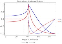
Reflection coefficients graphic[edit]
I suggest, if possible, that the autor of the graphics modifies them by plotting the coefficients for a refraction index of 1.5, more typical af a glass, which is the main material dealt with in the article. --GianniG46 (talk) 07:52, 15 June 2010 (UTC)
I suggest to include in the amplitude reflection coefficients the part beyond the critical angle of incidence for internal total reflection. I've quickly made this file:
but feel free to make a better one (which would perhaps include the transmission coeficients as well?) — Preceding unsigned comment added by Coussin00 (talk • contribs) 15:20, 19 April 2021 (UTC)
Transmittance to/through a medium[edit]
I just wanted to direct your attention to a recent disambiguation implemented in transmittance involving Fresnel equations: see here. Thanks. Fgnievinski (talk) 22:30, 9 March 2011 (UTC)
R+T must not equal to 1[edit]
There is a sentence in the article:
- As a consequence of the conservation of energy, the transmission coefficient in each case is given by Ts = 1 − Rs and Tp = 1 − Rp.[Hecht (1987), p. 102.]
This should be true *only if* R and T are defined in amplitudes.
However, the formula given in the article is in ratio of intensities:
i.e.

Although conservation of energy still applies (), the areas ,, are not the same. This means R+T should not be equal to 1! (except at normal incidence)


I wish to know what you think about it.--Antonysigma (talk) 16:05, 1 May 2011 (UTC)
- The article says "The fraction of the incident power that is reflected from the interface is given by the reflectance R and the fraction that is refracted is given by the transmittance T." So R + T = 1; these are not the intensities of the reflected and refracted light, but the fractions of incident light, which has no area difference effect. Maybe the issue is that transmission coefficient has a slightly different definition than the T here. It would not make sense for amplitudes, nor would it be quite right for intensities, but in the case of R, the incident and reflected beams have the same angle from the normal so they have the same areas, so the intensity ratio is the power ratio as specified. Dicklyon (talk) 16:12, 1 May 2011 (UTC)
- Thanks for your reply. So the equation won't be true unless the Fresnel equation is defined in power ratio, not amplitude ratio. Even this, there's still a conflict to formula of in the article, which is defined as intensity ratio. —Preceding unsigned comment added by Antonysigma (talk • contribs) 16:53, 1 May 2011 (UTC)


- Actually r + t ≠ 1 for electric field amplitude, because there is a change of dielectric permittivity when you change from one medium to another (Ei ≠ Er + Et). The relation R + T = 1 is correct for total power. It is also correct for intensity at the interface, since then there is no change in area, because the relevant area for all three beams is in the plane of the surface.
- It was wrong of you to delete that paragraph without discussing it first. The paragraph is supported by a citation to a reliable source. A reliable source always trumps any one editor's opinion, and usually for good reason.--Srleffler (talk) 01:17, 2 May 2011 (UTC)
- There is no conflict. The larger the incidence area is, the smaller the component of the speed perpendicular to that area will be. Dauto (talk) 13:18, 6 May 2011 (UTC)
- A wrote an explicit caveat in the article about this source of confusion.Fgnievinski (talk) 08:20, 7 January 2012 (UTC)
Graphs[edit]
The graphs shown are useful, but an index difference of n=1 to n=2 isn't very practical in real world situations. Practical examples with meaning to most readers will be 1/1.33 (air/water) or 1/1.5 (air/glass). Note that most practically common glasses occupy the narrow refractive index range between 1.45 and 1.55. In general, materials with refractive indices above 2 are very uncommon optical materials (though they of course exist). I suggest to redo the plots for 1/1.5 index contrast, if possible. — Preceding unsigned comment added by 13.2.16.151 (talk) 18:00, 14 June 2011 (UTC)
- They were made by User:DrBob, who seems to have stopped editing wikipedia two years ago. I agree that it's a worthwhile thing to do. It would take me a while to make it as pretty as DrBob did. I'm too busy now. Maybe someday. --Steve (talk) 19:39, 14 June 2011 (UTC)
- Nice job! :-) --Steve (talk) 02:17, 21 September 2011 (UTC)
- Nice. I just toned down the saturation of the lines so they aren't vivid red and blue, but other than that it's great. I've always thought n=1.5 would make more sense as an example. —Ben FrantzDale (talk) 13:01, 21 September 2011 (UTC)
- Not at all. When you are dealing with optical thin films there is usually a bigger change in the refractive index, e.g. air-Si (crystalline silicon 3.5), air-silicon monoxide (2.4), air-silicon dioxide,... or SU8 photoresist. --Javiucm (talk) 23:17, 30 October 2013 (UTC)
- I disagree with Javiucm. The purpose of that graph is not to tabulate values that professionals can read off the graph and use in their calculations. The purpose is to help typical readers get a better understanding of the fresnel equations. Typical readers have never heard of SU8 or silicon monoxide, but they have seen a lot of air/glass interfaces in their lives. So using that as an example will help those readers more easily relate to the fresnel equations. So again, if we have to pick one example, I think that 1:1.5 is good. Of course we don't have to pick just one example ... maybe there could be another figure showing how the parameters change with different refractive indices. :-D --Steve (talk) 19:28, 31 October 2013 (UTC)
Is there an error in the graph of Glass to Air amplitude coefficients? How can there be and in the portion of the graph corresponding to Total Internal Reflection? Kghandi (talk) 03:35, 1 November 2016 (UTC)


- The formula is
- (for s-polarization), where i is "initial medium" and f is "final". See my paper! For TIR, , so even if !
- So I would guess that the plot is correct. However, because (1) it's ugly (the fonts, the lines, etc.; should be SVG), and (2) it has no source code for us to verify its correctness, I think it should be redone, and I will do so at some point if someone else doesn't do it first. --Steve (talk) 19:28, 1 November 2016 (UTC)
![{\displaystyle T=|t|^{2}{\frac {\mathrm {Re} [n_{f}\cos \theta _{f}]}{\mathrm {Re} [n_{i}\cos \theta _{i}]}}}](https://wikimedia.org/api/rest_v1/media/math/render/svg/e8090f0da0f1cfe8ac36a77ef312bc20f19bfa51)
![{\displaystyle \mathrm {Re} [n_{f}\cos \theta _{f}]=0}](https://wikimedia.org/api/rest_v1/media/math/render/svg/bab1e1bfd784bef5cd764e954ca3a36b67a17fce)


- We do not expect any transmitted ray in the case of TIR. Do non-zero values of and in TIR represent the evanescent wave? Are these coefficients complex in the TIR case? I have just been reading Total_internal_reflection which is my first introduction to evanescent waves during TIR. If so, perhaps a brief statement to this effect would clarify the section. Kghandi (talk) 15:20, 2 November 2016 (UTC)


Amplitude[edit]
I cleaned up the new material on amplitude equations, and rearranged things a bit, but have not checked the equations themselves against a reference. It's not clear to me that the coefficients and the associated beam and field geometries are adequately defined, nor that the equations properly capture the phase of r and t. The construction has problems, in that it divides vectors to get a scalar quantity. As written and both equal , which is clearly wrong. I think the E's are just missing subscripts, as in the captions on the new images.


I don't have time to work on this any more right now, and more pairs of eyes looking at it is probably a good idea anyway. I am on record above as being opposed to incorporation of the amplitude equations into this article, but am willing to give it a chance if we can get them explained clearly and correctly, with the geometry and sign conventions fully defined.
Also on the to-do list: verify that these equations actually describe ratios of electric field amplitudes, as claimed in the text, and not the square root of intensity or some other quantity. It's been too long since I looked at the Fresnel equations for me to do that off the top of my head, but I've seen derivations that use square root of intensity and call it "E". --Srleffler (talk) 08:47, 18 December 2011 (UTC)
- I tried to clarify the conventions, although it's difficult without making pictures. I added a reference (Sernelius) which is typo-free, clear, and open-access. The textbooks I have seen all use exactly the same conventions as Sernelius except the opposite sign convention for .
- Anyway, people will presumably keep changing the formulas to agree with their textbook's conventions and definitions. With luck, I (or someone) will notice, and keep changing them back. :-/ --Steve (talk) 19:43, 18 December 2011 (UTC)
 | It is requested that a physics diagram or diagrams be included in this article to improve its quality. Specific illustrations, plots or diagrams can be requested at the Graphic Lab. For more information, refer to discussion on this page and/or the listing at Wikipedia:Requested images. |
--Srleffler (talk) 21:03, 18 December 2011 (UTC)

- The diagram at right may be suitable. The black arrows show the wave vectors (to scale, all with the same projection on the reflective/refractive surface), and the red arrows are all in the positive direction, or all in the negative direction, of the p vibrations. The "upside-down" incidence looks unconventional at first but has the advantages that (i) the x and y axes are in the customary directions, (ii) the incident direction is in the first quadrant, and (iii) the evanescent wave (if present) is a decaying exponential function of one of the coordinates.
- — Gavin R Putland (talk) 05:19, 7 May 2018 (UTC).
- As someone who has spent the past month implementing polarization ray tracing code, I really appreciated the description of the two different conventions. Understanding this saved me a great deal of time. It is quite valuable to have both described in the article. Kghandi (talk) 15:30, 2 November 2016 (UTC)
- Its late to reply after all this time - but I enhanced the notice (blanked out obviously) to reflect this fact in these edits [1][2]. -- F = q(E + v × B) 22:02, 23 February 2012 (UTC)
- I left the all-caps, but otherwise reverted you. A smaller notice in two places seems more useful than a very long notice in one.--Srleffler (talk) 02:14, 24 February 2012 (UTC)
- Sorry - I thought I copied and pasted the note in two places by accident, not realizing it was already there in two places, which is what I meant by my accidental duplication - I did NOT refer to it as someone else's mistake. I only tried to place more emphasis.-- F = q(E + v × B) 12:18, 24 February 2012 (UTC)
- I left the all-caps, but otherwise reverted you. A smaller notice in two places seems more useful than a very long notice in one.--Srleffler (talk) 02:14, 24 February 2012 (UTC)
- Its late to reply after all this time - but I enhanced the notice (blanked out obviously) to reflect this fact in these edits [1][2]. -- F = q(E + v × B) 22:02, 23 February 2012 (UTC)
- Becuase I would not like "people to keep changing the formulas to agree with their textbook's conventions and definitions", leaving it for others to keep changing them back, ":-/" (an insanley tedious process), why not request for an edit notice like this one for Maxwell's equations? It'll be more obvious than in the edit panel. At least its the first thing the editor will see anyway...-- F = q(E + v × B) 12:34, 27 February 2012 (UTC)
red-blue infographic[edit]
that is impossible for me to read (colorblind)... any way you can make it not red and blue? — Preceding unsigned comment added by 23.118.190.205 (talk) 14:45, 16 June 2014 (UTC)
- You can change it yourself ... just download Inkscape (or another svg editor), make changes, and upload a new version. (If the changes are drastic, you can upload it under a new filename rather than overwriting the old version.) [3] It might be even better if you move the labels to next to the lines, maybe with arrows from the labels to the lines, instead of putting the labels in a legend in the top corner.
- I found this tool that supposedly gives "color blind friendly" color schemes: [4]. Do you think it works? Maybe I'll use it in the future. (But I did not make any of those graphics myself.) --Steve (talk) 17:28, 16 June 2014 (UTC)
Propose switching sign convention for rp[edit]
For a while the article has used the sign convention for rp where positive means that the magnetic field's orientation does not change. That means that rs and rp have opposite signs at normal incidence. There is nothing incorrect about this, since it's just a convention and the article is consistent as written. But I do think the opposite sign convention for rp is more common and we should follow whatever convention is most common. Also, you can easily find statements in references like "Reflected light will experience a 180 degree phase change when it reflects from a medium of higher index of refraction and no phase change when it reflects from a medium of smaller index." [5], which is a nice clean statement to make but only works with the opposite sign convention for rp. (Well, it still doesn't work for p-polarization at very oblique angles, but it works in every other case!)
I actually switched it a while ago and was reverted, with the comment that we need to discuss on the talk page. So let's discuss! What do other people think? --Steve (talk) 13:24, 5 June 2015 (UTC)
- I don't have a problem with changing the sign convention in the article, as long as:
- There is a good reason for the change
- The change is applied consistently throughout the whole article
- The new treatment is supported by references that use the new sign convention, so that formulas can be verified by simple comparison with the reference.
- The last criterion is important. This article is subject to continual thrash as naive editors change signs and subscripts in formulas because the formulas don't match what's in their book, without consideration for the sign convention described in either the article or the text.[6][7][8][9] The proper way to deal with this on Wikipedia is what is prescribed in WP:OR: the treatment used in the article needs to be directly supported by a reference, so that there is a simple way to verify that the formulas are correct.--Srleffler (talk) 17:23, 6 June 2015 (UTC)
- By the way, I find the comment above about the phase change of light depending on the sign convention completely mystifying. It does not seem to me possible that this claim could be correct. A physical change in phase of light cannot possibly depend on an arbitrary choice of sign convention.--Srleffler (talk) 04:16, 10 June 2015 (UTC)
- Oppose. I'll second Srleffler's views. My impression is the article uses Hecht, and I recognize Hecht as a common college text on optics. I'll need citations to comparable sources to switch conventions. Glrx (talk) 15:38, 9 June 2015 (UTC)
Update: I checked 6 mainstream textbooks, and I found 3 of each convention!
- Agrees with wikipedia now (rp > 0 for light in air reflecting off glass at normal incidence):
- Jackson (Eq. (7.41)),
- Hecht (Eq. (4.38)),
- Zangwill (Eq. (17.34))
- Agrees with change I'm proposing (rp < 0 for light in air reflecting off glass at normal incidence):
- Feynman Lectures on Physics (Eq. 33.8).
- Griffiths (3rd edition, Eq. (9.109)),
- Lipson-Lipson-Lipson (Eq (5.42)),
So I was incorrect when I said above that the rp<0 convention is "more common". Sorry! :-P
Hecht is a widely used and respected textbook, as Glrx rightly points out, but then again so is Griffiths, and Feynman, and Jackson for that matter. I think it's more-or-less a tie.
Srleffler: When light in air reflects off glass at normal incidence, the electric field switches sign (or you could say, it changes phase by pi), while the magnetic field keeps the same sign (or you could say, it changes phase by 0). Related to this, there are two ways to define the relative phase of oppositely-propagating light beams, the one based on whether the magnetic field is in phase or not, and the one based on whether the electric field is in phase or not. These two conventions line up with the two possible signs of rp.
Is one convention better than the other? Normally we care a lot more about the relative phase of the electric field, not magnetic field, because the electric field plays a much bigger role in light-matter interaction. The change I'm proposing is consistent with that preference. After that change, at normal incidence, we would be describing light as out-of-phase or in-phase based on the electric field, whereas with the current sign convention it's based on the magnetic field.
However, at glancing angle, that's no longer true. At glancing angle, the convention currently in the article is clearly superior to the one I'm proposing...
Given that, I'm starting to think that the convention in the article is best after all. Never mind. Thanks for the feedback :-D --Steve (talk) 21:59, 10 June 2015 (UTC)
Why do you think that the convention used is superior to the one you actually proposed at glancing angle? Somehow I'm also confused since Hecht 4th Edition states in (Eq. (4.38)) that there is no phase shift for normal incidence for the E-field. Am I mixing something up? Asdfawer2 (talk) 22:51, 26 July 2015 (UTC)
- Asdfawer2: I'm looking at Hecht 4th edition around Eq. 4.38 and I don't see anything that says "there is no phase shift for normal incidence for the E-field". Can you be more specific? Are you referring to higher-index-to-lower-index reflection or lower-index-to-higher-index reflection? (Because those two cases are opposite reflection phases.)
- As I said before, for normal-incidence reflection, the incident and reflected waves are traveling in opposite directions. One possibility is that their electric fields are in phase (at the interface) while their magnetic fields are out-of-phase. Another possibility is that their magnetic fields are in phase while their electric fields are out-of-phase. There is no obvious natural way to say which of these two possibilities is "0 phase shift" and which is "pi phase shift".
- On the other hand, for glancing angle, the incident and reflected light are essentially traveling the same direction. So there is a unique and natural and "correct" way to say whether the waves are in or out of phase at the interface. For example, if you tell me "r=-1 at glancing angle", then I would infer that the reflected light is equal and opposite to the incident light, so I would expect destructive interference at the interface (both zero electric field and zero magnetic field). That's what you expect, and that's what you get with the Jackson/Hecht/Zangwill/wikipedia convention, but that's the opposite of what happens with the Feynman/Griffiths/Lipson convention (which says destructive interference occurs when r=+1). --Steve (talk) 14:22, 29 July 2015 (UTC)
Again, I just mean not even in Hecht the formulas seem consitent (from my point of view).
Looking at Eq. 4.32 for normal incidence at an interface from lower to higher refractive index he states , since . Eq. 4.38 yields . Since Hecht defines the reflection coefficients including the phaseshift, as there may only be a phaseshift of pi or 0, resulting in . For me its not clear how you would argue that you could infer a phase relation for any angle. Of course I agree with you in the extreme cases its obvious how the signs should look like, I just mean we could state more precisely what each reflection coefficient stands for, e.g. , in the currently used convention, which from my point of view does ""not"" agree with Hecht.


- Since one is not able to define a plane of incidince in the normal-incidence-case, the formulas apparently do not work straightforward in that case. But what is then the phase-shift, using rp would lead to a different result than using rs.
I hope I could clarify my point.
Asdfawer2 (talk) 00:11, 5 August 2015 (UTC)
EditAsdfawer2 (talk) 00:57, 5 August 2015 (UTC)
Special cases[edit]
Why is there an empty section called "Special cases"? — Preceding unsigned comment added by 129.242.204.238 (talk) 07:47, 25 October 2016 (UTC)
Notation: s and p[edit]
I disagree with this edit. The s and p should not be given "math" formatting when they appear in plain text, because they are not mathematical objects notwithstanding the fact that they appear in the equations as labels on variables. "S polarization" and "p polarization" are simply the English names for these two characteristics. I prefer them in italics, per Italic type#Usage, "Using a letter...mentioned as itself", but I'm open to arguments that that doesn't apply here because the s and p are not truly referring to themselves in this case. They should still be in italics in their first appearance in the text, however, as "Introducing or defining terms, especially technical terms or those used in an unusual or different way."--Srleffler (talk) 02:17, 14 November 2016 (UTC)
- The Italic type#Usage is not persuasive. The letters are not referring to letters but rather names that can be viewed as constant variables: the value of variable x changes over time or distance or whatever; units, such as cm an eV, are not variables and are not italicized; the value of the function sin is constant, so it is not italicized (and needs spacing rules).
- The context for the "John" example need not contend with other italic usage conventions such as italics being used for variables. When we say s, are we talking about the letter "s" or the variable s or the subscript that will actually appear in the math markup as s. The current markup in the article has no ambiguity; the same font and slant are used for the same ideas. Your proposed change would introduce inconsistency. I see no good reason to use sans serif italic letters in the text when they are used to explain the serif normal letters in the math markup. Don't confuse the reader with different fonts and slants for the same notion.
- The argument that terms should be introduced in italics is likewise confusing to the reader. The Roman font shift is enough of a cue to the reader. Furthermore, introducing terms usually refers to introducing words or phrases such as "unit vector" rather than letters. If I were to slavishly follow an italicization rule, I would introduce the unit vector î as î; that wrecks a convention about using normal fonts for unit vectors and italic fonts for variables. Enforce one convention and break others? Glrx (talk) 03:37, 14 November 2016 (UTC)
- I'm fine with not using italics if you don't find that argument persuasive. The s and p should not be in the math font, though. When "s" appears in a phrase like "s polarized", it is not a reference to a symbol appearing in the equations. "S polarized" is the plain English description of the property. If an article used a subscript "n" for "normal" on a variable in an equation, you wouldn't insist on making the word normal appear as normal or normal in the body of the article. This is no different. "S polarization" is a phrase, not a reference to a mathematical symbol. --Srleffler (talk) 05:45, 14 November 2016 (UTC)
- I can live without the math font for s and p. (If saying senkrecht, convention would be to italicize it as a foreign word.)
- There's another point of confusion: should it be "s polarization" or "s-polarization"? Article currently uses both (which may be my fault). Two conventions:
- Treat "s" as an adjective for the noun "polarization", so the terms should be "s polarization". In contrast, the phrase "s-polarized light" needs the hyphen to show that "s" modifies adjective "polarized" rather than light. Consequently "s polarization" and "s-polarized". See, for example, https://www.rp-photonics.com/spotlight_2012_03_03.html
- Others use noun "s-polarization" and adjective "s-polarized". I do not see a grammar rationale for this usage. See http://www.iiviinfrared.com/resources/polarization.html
- Neither of those websites are RS. See also MOS:HYPHEN.
- I'd go with the first but could be persuaded otherwise if significant RS are using "s-polarization". Glrx (talk) 20:05, 14 November 2016 (UTC)
- I'm fine with not using italics if you don't find that argument persuasive. The s and p should not be in the math font, though. When "s" appears in a phrase like "s polarized", it is not a reference to a symbol appearing in the equations. "S polarized" is the plain English description of the property. If an article used a subscript "n" for "normal" on a variable in an equation, you wouldn't insist on making the word normal appear as normal or normal in the body of the article. This is no different. "S polarization" is a phrase, not a reference to a mathematical symbol. --Srleffler (talk) 05:45, 14 November 2016 (UTC)
Missing variable identification[edit]
The u and the epsilon are missing identification in the equations of reflectance. I assume u is the magnetic moment and the epsilon is the dielectric constant. Also, in the portion between reflectance for magnetic and magnetic materials can we say..... " for materials that are repeled by a magnetic field" instead of "materials that are not magnetic". Both are technically correct but all materials have magnetic properties so it might be less confusing if we chose to incorporate something like "materials that repel a magnetic field." TerpeneOtto (talk) 00:24, 21 January 2017 (UTC)
- μ is magnetic permeability and ε is electric permittivity. "Materials that are not magnetic" is shorthand for the technical statement "Materials for which μ≈μ0 (where μ0 is permeability of free space). That's not the same as "Materials that are repelled by a magnetic field". The latter is a reference to diamagnetic materials, i.e. μ < μ0. A diamagnetic material can be "not magnetic" in practice if μ is only slightly less than μ0, and likewise a paramagnetic material can be "not magnetic" in practice if μ is only slightly greater than μ0. So being diamagnetic is not directly relevant.
- By the way there's also a big difference between a DC magnetic field and a 500000000000000 Hz oscillating AC magnetic field (as in visible light), so that a material repelled by the former may not be repelled by the latter and vice-versa. "Materials that are repelled by a magnetic field" implicitly means DC magnetic field, so is doubly misleading in this context. --Steve (talk) 22:33, 22 January 2017 (UTC)
- Sbyrnes321 can you input the variable identification for the u2 and the E2? Under the power and intensity equations portion, we need to recognize that the magnetic moment and the dielectric of the material are part of the equations and are represented by the previous variables. I realize the top paragraph was a little blah. I tried to connect the phrase "materials that are not magnetic" with a way to generic definition of non-magnetic materials I found online. I had a hard time connecting the articles phrase and the bad definition to my knowledge of magnets because the phase "materials that are not magnetic" is not technical enough. Is there anyway we could expand this phrase into something a little more technical? could you just replace "materials that are not magnetic" with something else? We could just add a mathematical definition in parentheses after it. I appreciate your technical explanation in your first paragraph. TerpeneOtto (talk) 07:19, 24 January 2017 (UTC)
Plots of amplitude/power coefficients versus angle of incidence[edit]
On 2017-11-05 I have replaced the plots for coefficients versus angle of incidence for air to glass and vice versa, for both amplitude and power coefficients, with substantially improved ones. The old plots by Ulflund (power coefficients) were very good, but showed only the values for reflection. The old plots by Kohlik17 showing the modulus of the amplitude coefficients were of low resolution and, in the case of glass-to-air, suffered from a limited vertical range hiding the important t>1 regime, and showed nonzero transmission in the TIR regime, which is just wrong physics. The new plots add power transmission, Brewster's angle for power plots, as well as expressions for the normal incidence limit as a function of . I tried to keep as many of the good things from Ulflund's plots as possible. Numerically, the new plots agree with the old ones by Ulflund, and for the amplitude coefficients I have checked them against 4th Ed. of Hecht. They are submitted in SVG format. The generating Python code will be shared when I get around to it.

I hope this edit is in line with how things are done here! Otherwise, please do let me know. Suggestions for further improvement welcome. Sbergjohansen (talk) 11:50, 5 November 2017 (UTC)
- Thanks. These new graphs look much better. You're right there were some serious problems with the old amplitude graphs. One important question: Have you used the same formulas for amplitude coefficients as given in this article? There are several different conventions used in the literature, so if you used formulas from some other source the results won't match the formulas given here.--Srleffler (talk) 16:02, 5 November 2017 (UTC)
- Yes - the new graphs use the sign convention of the article! And thank you too, Srleffler, for keeping a close eye on this and many other important details. I will post the sources as soon as I have figured out the best way to do it. Sbergjohansen (talk) 18:02, 5 November 2017 (UTC)
Derivation section?[edit]
Notice: Having added the "History" section, I'm now working on a "Derivation" section, covering both the "more general" case and the non-magnetic case. — Gavin R Putland (talk) 09:07, 16 May 2018 (UTC).
- @Gavin R Putland: Great, but I really think you should NOT introduce any mu≠1. It makes the derivation and results more complicated, without any use in actual problems. Until I added E-M radiation in a parenthetical phrase recently the stated scope of the article was light, period. Just use the simple definitions n=sqrt(eps) and eta = eta0/n, all components of H continuous across the interface. Including mu doubles the number of parameters and is essentially NEVER used in practice. I'm assuming you'll more or less transfer the entire section 2 of Fresnel Rhomb up to eq. 12 (but not assuming n2==1) to this page and transfer eq 13-15 to the TIR page (referring to this page), and leave only sec 2.6 in the Rhomb page (referring to the TIR page) which is all that belongs there. Thanks, Interferometrist (talk) 15:22, 16 May 2018 (UTC)
- @Interferometrist: This argument came to my notice when my draft was at an advanced stage. At the risk of seeing my work disappear, I offer several counter-arguments. (1) Allowing a general μ doesn't increase the number of parameters that must be carried, provided that everything is expressed in terms of the one essential parameter, namely the intrinsic admittance (or its reciprocal). (2) If we then put μ = μo, the admittance becomes proportional to the refractive index, so that all the results can be rewritten in terms of refractive indices in one step. (3) In consequence of that "one step", many results in terms of refractive indices are dumped in one place for easy reference. (4) The connection between admittance and refractive index must be made somewhere. It might as well be placed for maximum advantage. (5) Of all the results to be derived, the only ones that depend on non-magnetic media are Brewster's relations (complementarity of angles, and the arctan formula) and Fresnel's sine and tangent laws. It is desirable to show that dependence, especially if it can be done with negligible extra work. (6) The article already expresses reflectivities in terms of impedances. One would expect a "Derivation" section to include some justification of those statements. IMHO, Gavin R Putland (talk) 11:06, 17 May 2018 (UTC).
- It's not clear to me that derivations are in our scope. Wikipedia is not a textbook. While people often do add derivations to articles, this is often a mistake. Our focus should be on explaining what the equations are, how they are used, and their history. Derivations are best left to the textbooks, unless they somehow add to the user's understanding of the result.--Srleffler (talk) 03:37, 17 May 2018 (UTC)
[Above exchange moved from earlier on this page] Interferometrist (talk) 16:29, 17 May 2018 (UTC)
- @Srleffler: You're right that the derivation isn't needed but the way this started is on the Fresnel Rhomb page where User:Gavin R Putland included a more general derivation for the reflection coefficients just in order to explain the phase shift between polarizations. My reaction was (and is) that this didn't belong there but should just refer to the TIR page, and the results of the TIR page should just be a special case for the Fresnel coefficients whose derivation should be on this page. And that the derivation shouldn't interfere with the more casual reader so should be at the bottom in each case. You're right, that the page doesn't need to have the derivation, but if he wants to include it that's ok.
- @Gavin R Putland: - Now if I understand you about including mu, then you're wrong, it isn't that simple. I'm not sure what you're starting from, but if you work it all out (as I did myself some years ago) then you find that indeed there are twice as many parameters, now 4 (possibly complex) material parameters governing an interface. They do NOT collapse. Each medium has a characteristic impedance ~ sqrt(mu/eps), and a refractive index (or 1/k_0) ~ sqrt(mu*eps), and these act separately. The one symmetry I'm aware of is that if you switch E and H everywhere (which does not affect the power) and switch relative epsilon and mu, and switch polarizations, then you get the same results. But that's it. Varying both, you get more unfamiliar situations like refraction with no change in wave impedance (thus no reflection) when mu_rel = eps_rel. For the p polarization I computed Fresnel coefficients using the "directive impedance" (ratio of E to H in the x-y plane only for a given k_x) and for the s polarization the directive admittance -- clearly these are not generally reciprocal. I DO think that there should be a conceptual distinction made between the impedance effect of n and its effect on k, so including mu explicitly does make that clear. But it can also just be stated: eps = eps0*sqrt(n), z=z0/sqrt(n). The reason not to include mu is that almost no one is ever going to use it in practice, and the increased complications of including it can only make the derivation more difficult to read. That's my view! Interferometrist (talk) 16:29, 17 May 2018 (UTC)
- Also, I would recommend that the derivation itself NOT mention the refractive index n (until the end) but just be in terms of electromagnetic quantities, thus epsilon, or (preferably) epsilon_rel so that epsilon_0 and mu_0 are included as constants that eventually get combined in terms of eta_0 and c. Then at the end substitute eps_rel = n^2 to obtain practical formulas. Just my 2 cents :-) Interferometrist (talk) 16:44, 17 May 2018 (UTC)
- @Interferometrist: Sorry if I seem to be ignoring you; the notification of your reply didn't come through, although this page is on my watch list.
- Yes, the impedance and the refractive index act separately, but the impedance (or admittance) is the one that affects the reflection/transmission ratios — unless we express everything in terms of a single angle, in which case the refractive index explicitly enters the equation instead of the other angle; but as long as we carry two angles in the equations, using Y instead of n doesn't complicate things further, but merely gets closer to the cause.
- I have covered the switching of E and H in a sort of a fashion, by considering a common epsilon instead of a common mu (in the last section of the appendix).
- My impedance and admittances are "intrinsic" or "characteristic", not "directive". (And did you mean the xy plane or the plane of the interface?)
- I have covered reflection without refraction. Concerning refraction without reflection, I wonder whether your comment is based on directive impedance instead of intrinsic impedance. It seems to me that if the permeabilities are unequal but in the same ratio as the permittivities, then, by (4) and (5), we will have equal intrinsic admittances but unequal refractive indices, hence unequal angles at non-normal incidence, so that, by (15) and (23), we will have no reflection at normal incidence; but by (13) and (21) we will still have some reflection at non-normal incidence, because the terms in the numerators won't cancel, because the (intrinsic) admittances will match but the angles won't.
- It turns out that I have followed your recommendation to introduce n as late as possible, but I seem to have arranged things so as to make the introduction of n simpler than you expected.
- In summary, I am hoping that our apparent disagreement is based on confusion between directive and intrinsic admittances.
- — Gavin R Putland (talk) 06:54, 20 May 2018 (UTC).
P.S.: If my "Appendix: Theory" and its title are going to survive, it might be desirable to redirect "Derivation of Fresnel equations" and "Derivation of the Fresnel equations" to that appendix. — Preceding unsigned comment added by Gavin R Putland (talk • contribs) 07:25, 20 May 2018 (UTC)
P.P.S: I am still suffering afterthoughts. Neither the old text nor my new appendix is yet consistent with the convention that the real part of the Poynting vector is related to average power. My appendix is also loose in its use of the term "magnitude". I shall attend to these matters ASAP. — Gavin R Putland (talk) 15:29, 20 May 2018 (UTC).
- @Gavin R Putland: Great work! That was a lot of editing on your part. I have a number of changes and will explain them in context, and if there are any disagreements just raise them here. Please don't take offense as I appreciate all the work you did but don't have time to compliment you at every point. I'll mention a couple general or stylistic disagreements here.
- But first, on your response concerning using mu!=1: I might have been wrong and that the solution is as easy as you did it. I will compare yours to my results for a few such cases (I can't compare the equations because they're totally different: I don't use angles or trig functions). My apologies if that is the case.
- On notation, I would really have preferred to see Z rather than Y. "Admittance" is a term that most physicists wouldn't even recognize whereas impedance is a very familiar concept.
- @Interferometrist: OK, but one doesn't solve that problem by deleting the one subsection that refers to impedance, especially when that breaks the last subsection. One solves it by reworking the whole derivation in terms of impedance, which is rather a big job.
- I can think of 8 or 10 impedance-like measures in physics whereas almost none that are admittance-like (I can only think of "compliance"). The point is to make it as easy to read and understand as possible for the likely readership.
- @Interferometrist: If we're going to allow examples that don't have the dimensions of admittance but are merely proportional to admittance, we could include not only compliance but also capacitance and... permittivity. For what it's worth, I used admittance instead of impedance because for non-magnetic media, n is proportional to Y, not Z. Using Z would introduce an extra step in the conversion to n, namely clearing the numerators and denominators of reciprocals, causing an interchange of subscripts.
- I also would have suggested using theta_1 and 2, for media 1 and 2, rather than i and t where you have to make the translation in your mind i=1, t=2. Then the equations are a little more transparent. But it's a lot to change and the figure would also need to be changed -- you made it yourself and I don't know if doing that would take 2 minutes or 2 hours (in which case don't do it!).
- @Interferometrist: Using subscripts 1 and 2 would match Sernelius; but using i and t matches Hecht and Born & Wolf (and the first diagram in the article, and my diagram for total internal reflection).
- I'm finding a few errors where the equations only work for real numbers which I'll change.
- @Interferometrist: Yes, that's what I mean by my "loose" use of the word "magnitude". For linear polarization, a complex vector is unnecessarily general; it suffices to use a constant unit vector multiplied by a complex scalar. I shouldn't call that scalar a "magnitude" because that suggests that it is real. "Scalar phasor"? "Complex magnitude"? "Complex length"? On this matter, although I have already spent more time than I bargained for, I find myself wishing I had spent more before I uploaded the work.
- Also some wording etc. I will also make some changes earlier in the page and also on the TIR and Rhomb pages. I won't finish now but more later and will look for any feedback from you. More later, Interferometrist (talk) 18:17, 20 May 2018 (UTC)
but by (13) and (21) we will still have some reflection at non-normal incidence
- Yes you are absolutely right! But no reflection at normal incidence is already notable, and the principle of mu_rel = eps_rel everywhere IS used extensively by proponents of "transform optics" with continual changes of n (~ GRIN lens) in which case there is only refraction and independent of polarization for this special case (that I don't consider very important, let alone practical!). Interferometrist (talk) 18:25, 20 May 2018 (UTC)
- One more general style issue I was going to mention is that almost everyone (I believe) in a 3-D problem uses Z for the direction of propagation, whereas you have interchanged Z and Y from what I'd expect.
- @Interferometrist: OTOH, some people expect that x is to the right and y is up. But I can change two diagrams if I have to.
- Have you seen it this way with Y? Of course it's arbitrary except for one thing: with X-Y propagation (say normal incidence) in the Z direction then if E is in X then H will be in +Y. But if X-Z then it's minus (if a right handed coordinate sys). You avoided that by specifying:
So, for the incident, reflected, and transmitted H fields, let the respective components in the −z direction be Hi , Hr, Ht .
- That's a really bad form in my book. It should just be called H_z which everyone understands. Change to XY and that minus goes away (but reappears for the s polarization, but then DO put in the minus but IN THE EQUATION, not the definition of something that should have a clear understanding like H_x,y etc. It wouldn't be too hard to change between Y and Z (and between H_-z and -H_z) but they would all have to be done together so I'll see if you want to do it or if you even agree. Interferometrist (talk) 18:45, 20 May 2018 (UTC)
- @Interferometrist: I did it that way in order to re-use the red arrows. A possible compromise is to let H be in the positive z direction and let E be against the red arrows, with consequent changes in the equations.
- Also, is the term "transmissivity" actually used? I never hear it and if I did I'd ask the speaker about it. So I'm asking you all now. This was in the article before but is repeated in the derivation section. Interferometrist (talk)
- @Interferometrist: "Reflectivity" and "transmissivity" (mentioned in the article on "Radiation properties") imply that we mean one interface, not the combined effect of multiple interfaces. If we use "reflectance" and "transmittance", the fact that we mean one interface becomes a matter of context. I don't have a strong preference on that.
- — Gavin R Putland (talk) 03:23, 21 May 2018 (UTC).
Latest replies[edit]
@Gavin R Putland: and anyone else listening: I'm a bit busy and will respond quickly to some of your points:
- I pointed out a couple places that I would have used a different convention, but really none of these are too important. A person capable of understanding the math can easily adapt to the reciprocal of impedance or rotated axes. The one that I would have found the most difficult if I were reading it from scratch is having to remember i=1 and t=2. A derivation on Wikipedia doesn't need to follow the conventions of any author, but I try to avoid clashes with common conventions such as the orientation of the coordinate system. But again, anyone who could understand it still can, and there's probably no point in changing a convention once this has all been written.
For linear polarization, a complex vector is unnecessarily general; it suffices to use a constant unit vector multiplied by a complex scalar.
- No, actually you are wrong. A complex epsilon or mu (attenuating medium) leads to a k which is a general complex vector (a real vector plus j* a different vector in a different direction). The derivation you wrote already does that, you just didn't realize it! (It's buried in the "complex angles," which I abhor!). For instance, with TIR consider the field in medium 2 (kx real, kz imaginary). When epsilon or mu are complex the medium supports inhomogenous waves in which the direction of wavefronts and the direction of power flow are different. And all that works fine now. My only point was that it is more confusing to have a quantity X which multiplies a unit vector defined as -yhat rather than just saying -X times yhat or -X being the y component of something. There wasn't any real need for the e_k unit vector so I took it out.
OTOH, some people expect that x is to the right and y is up. But I can change two diagrams if I have to.
I did it that way in order to re-use the red arrows.
- Those comments seem to indicate you didn't understand my remark about the coordinate system. But as I said, you could probably leave it the way it was written.
- A lot of your writing is really long-winded (I understand as I have the same problem!). So in a number of places I've made it more concise or removed content that was duplicated elsewhere or offloaded content where wikilinks suffice. In a few cases I identified content that I'm hoping YOU will fix, such as section 6.10 which should just be a short paragraph and the ending moved to the history section. I hope you have been looking at the edit summaries, not just the result.
- Yes, you got me! Capacitance is a common admittance-type term.
- I was wrong about what I imagined to be the complexity of including mu≠1. Indeed your results appear fine, I apologize. I also had never realized (of course it's a situation not to be seen in practice) of the unusual results when mu~1/epsilon, n=constant across an interface!
- Forget what I said about Brewster angle when mu changes. It's really messy (including s-polarized Brewster transmission) and of course of no practical importance.
.... especially when that breaks the last subsection.
- I don't know what you're referring to here. If I "broke" something, then fix it! Nothing I do is irrevocable. If you don't like a change, you can revert it (up to 3 times a day, without getting into trouble). Or better, discuss it, or just change it "back" in a way that addresses the reason that someone else did it differently. But I don't know what I broke so I can't fix it myself.
OK, but one doesn't solve that problem by deleting the one subsection that refers to impedance
- As I said in the edit summary, having a section just explaining how to use the reciprocal of a quantity isn't needed for an article/section that could only be understood in the first place by someone conversant in such math. There was no actual "problem", just my suggestion that "impedance" is a much more accessible term.
- Gavin: I'd appreciate it more if you could put all your replies in one block rather than interspersed with what you're replying to. Otherwise I don't find it easily. If needed, requote the content you're replying to (as I have here). Thanks again for your hard work! Interferometrist (talk) 16:31, 22 May 2018 (UTC)
n₁ and n₂[edit]
The formulae after ‘Making this substitution, we obtain equations using the refractive indices:’ seem to me to only depend on n = n₂ / n₁ and not on n₁ and n₂ separately.
Could you be a bit more specific? Can't you divide by n₁ above and below the division lines in the expressions for Rs and Rp?
- Yes, you're right...I didn't look at it closely enough.--Srleffler (talk) 21:24, 26 September 2021 (UTC)
It's a request....[edit]
Please add a photo on 's and p polarization' to describe it. Himadrichakrabortydip (talk) 15:05, 15 May 2022 (UTC)
Gentle request with exceptional ideas[edit]
Overview
In overview section, it is said "The equations assume the interface between the media is flat and that the media are homogeneous and isotropic. The incident light is assumed to be a plane wave, which is sufficient to solve any problem since any incident light field can be decomposed into plane waves and polarizations".
However, I think it is important to add this content in order to have a more complete explanation:
Also, media are non-absorbing, meaning that the refractive index is a real value. the methodology below is a great approximation for weak absorbing media however, at strong absorbing media (as plasmas) different expressions are valid, known as generalised Fresnel Equations [1].
Complex amplitude reflection and transmission coefficients
In complex amplitude reflection and transmission coefficients section it is said that "The equations consider a plane wave incident on a plane interface at angle of incidence, a wave reflected at angle , and a wave transmitted at angle. In the case of an interface into an absorbing material (where n is complex) or total internal reflection, the angle of transmission does not generally evaluate to a real number. In that case, however, meaningful results can be obtained using formulations of these relationships in which trigonometric functions and geometric angles are avoided; the inhomogeneous waves launched into the second medium cannot be described using a single propagation angle."
I think that is important to add this sentence:
The more complete theory must be used, which considers two different angles: one for the equi-phase versor (wave propagation direction) and the other for the equi-amplitude versor (wave attenuation direction) [2].
Multiple surfaces
To a more complete Multiple surfaces section, from published research work, this content is important to be here:
Moreover, the decomposition of the rays propagation into a geometric series allow us to use novel methods as the ones presented in [1] [3]
[1].
[3].
[2].
WhoIsD (talk) 15:42, 10 May 2023 (UTC)
- The title captched my attention. I read the suggestions and I had already read some of the references.
- In my point of view, @WhoIsD presents a excellent text, with great readability and that allow us to understand (better) the topics in question. 2001:690:2100:C0:B013:A4D7:B866:E09A (talk) 16:33, 10 May 2023 (UTC)
References
- ^ a b c Marques Lameirinhas, Ricardo A.; N. Torres, João Paulo; Baptista, António; M. Martins, Maria João (Aug. 2022). "A new method to analyse the role of surface plasmon polaritons on dielectric-metal interfaces". IEEE Photonics Journal. 14 (4). doi:10.1109/JPHOT.2022.3181967.
{{cite journal}}: Check date values in:|date=(help) - ^ a b Marques Lameirinhas, Ricardo A.; N. Torres, João Paulo; Baptista, António; M. Martins, Maria João (Aug. 2022). "A Novel Analysis for Light Patterns in Nano Structures". IEEE Photonics Journal. 14 (6). doi:10.1109/JPHOT.2022.3227429.
{{cite journal}}: Check date values in:|date=(help) - ^ a b Marques Lameirinhas, Ricardo A.; N. Torres, João Paulo; Baptista, António; M. Martins, Maria João (Aug. 2022). "A New Method to Determine the Response of Kretschmann's Structure-Based Biosensors". IEEE Sensors Journal. 22 (21). doi:10.1109/JSEN.2022.3207896.
{{cite journal}}: Check date values in:|date=(help)
Correct power transmission coefficients for complex media[edit]
In the "Complex amplitude reflection and transmission coefficients" section, the given equation for power transmission coefficients for complex media is

But I don't think this equation can be correct. If


Based on my own derivation, I believe the correct expression (applicable to either polarization) is

![[3]](https://commons.wikimedia.org/wiki/File:Fresnel_reflection.svg)
I'm hesitant to change the page based on my derivation alone, but in the books I have and the bit of googling I did, I didn't find anything on this topic. I don't have access to the source quoted here ([1]).
Would anyone else have any sources that confirm (or deny) my assertion? Perhaps someone has a copy of that Hecht book and could double-check what it says. I'd be happy to post my derivation here if anyone would like to see it. Homm2trschell (talk) 17:11, 14 July 2023 (UTC)
- I don't have time to look into this right now, but you are most likely wrong. The definitions and sign conventions mess everyone up the first time through this material.--Srleffler (talk) 20:59, 15 July 2023 (UTC)
- I have an earlier edition of Hecht. The formula at the top is correctly transcribed.--Srleffler (talk) 21:04, 15 July 2023 (UTC)
References
- ^ Hecht, 2002, p. 120, eq. (4.57).
- C-Class vital articles
- Wikipedia level-5 vital articles
- Wikipedia vital articles in Physical sciences
- C-Class level-5 vital articles
- Wikipedia level-5 vital articles in Physical sciences
- C-Class vital articles in Physical sciences
- C-Class physics articles
- High-importance physics articles
- C-Class physics articles of High-importance
- Wikipedia requested physics diagrams